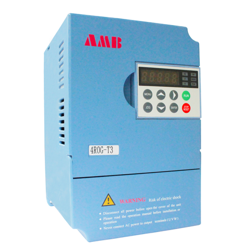
Induction motor, also known as "asynchronous motor", is a device that puts the rotor in the rotating magnetic field, under the action of the rotating magnetic field, obtains a rotational torque, so that the rotor rotates. The rotor is a rotatable conductor, usually in the form of a squirrel cage. It was invented by electrical engineer Nicholas Tesla in 1887. The article introduces the concept, inventor, working principle, basic structure, working mode, braking mode, asynchronous characteristics, specifications and fault inspection of induction motor.
Through the relative motion between the rotating magnetic field generated by the stator (whose speed is synchronous speed n1) and the rotor winding, the rotor winding cuts the magnetic induction line to generate the induced electromotive force, thus making the induced current in the rotor winding. The induction current and magnetic field in the rotor winding act on each other to produce electromagnetic torque and make the rotor rotate. When the rotor speed is close to the synchronous speed, the induction current decreases gradually, and the electromagnetic torque is also reduced accordingly. When the asynchronous motor works in the motor state, the rotor speed is less than the synchronous speed. In order to describe the difference between rotor speed n and synchronous speed n1, slip is introduced.
Basic structure
Basic structure of single phase asynchronous motor
Single phase asynchronous motor is a motor which only needs single-phase AC power supply. Single phase asynchronous motor consists of stator, rotor, bearing, casing, end cover, etc. The stator is composed of frame and core with winding. The core is made of silicon steel sheet by punching and laminating. Two sets of main winding (also known as operation winding) and auxiliary winding (also called starting winding) are embedded in the slot, which are separated by 90 ° electric angle. After that, connect the auxiliary winding to the main winding or the AC power supply. The rotor is cage type cast aluminum rotor. After the iron core is laminated, the aluminum is cast into the slot of the iron core, and the end ring is cast together to make the rotor bar short circuited into the squirrel cage type.
Single phase asynchronous motor is divided into single-phase resistance starting asynchronous motor, single-phase capacitor starting asynchronous motor, single-phase capacitor running asynchronous motor and single-phase double value capacitor asynchronous motor.
Basic structure of three phase asynchronous motor
Three phase asynchronous motor is mainly composed of stator, rotor and bearing. The stator is mainly composed of iron core, three-phase winding, frame and end cover. The stator core is usually made of 0.35 ~ 0.5 mm thick silicon steel sheet with insulating layer on the surface. There are evenly distributed slots in the inner circle of the core to embed the stator winding. The three-phase winding is composed of three identical windings with the same structure arranged at 120 ° electrical angle in space. Each coil of these windings is embedded in each slot of the stator according to certain rules. Its function is to pass in three-phase alternating current to produce a rotating magnetic field. The frame is usually cast iron, the frame of large asynchronous motor is welded with steel plate, and the frame of micro motor is made of cast aluminum. Its function is to fix the stator core and front and rear end covers to support the rotor, and play the role of protection and heat dissipation. There are cooling ribs outside the frame of the enclosed motor to increase the heat dissipation area. The end covers of the frame of the protective motor are provided with ventilation holes, so that the air inside and outside the motor can be directly convective to facilitate heat dissipation. The end cover is mainly used to fix the rotor, support and protect. The rotor is mainly composed of core and winding. The material of the rotor core is the same as that of the stator. It is made of 0.5 mm thick silicon steel sheet, and the holes are evenly distributed on the outer circle of the silicon steel sheet, which is used to place the rotor winding. The stator core is usually used to punch the inner circle of silicon steel sheet behind to punch the rotor core. Generally, the rotor core of small asynchronous motor is directly pressed on the rotor shaft, while the rotor core of large and medium-sized asynchronous motor (rotor diameter more than 300 ~ 400 mm) is pressed on the shaft with the help of rotor bracket. Rotor and rotor winding are divided into rotor winding and rotor winding. (1) Squirrel cage rotor: the rotor winding is composed of several guide bars inserted into the rotor slot and two ring end rings. If the rotor core is removed, the whole winding looks like a squirrel cage, so it is called cage winding. Small cage motor adopts cast aluminum rotor winding. For motors above 100kW, copper bar and copper end ring are welded. Squirrel cage rotor can be divided into impedance rotor, single squirrel cage rotor, double squirrel cage rotor and deep groove rotor. Starting torque and other characteristics are different. (2) Wound rotor: the wound rotor winding is similar to the stator winding. It is also a symmetrical three-phase winding, which is generally connected in a star shape. The three outgoing terminals are connected to the three collector rings of the rotating shaft, and then connected with the external circuit through the brush.
operation mode
Starting mode of asynchronous motor
1.1 soft start
With the rapid development of microcomputer control technology, a number of electronic soft start controllers have been successfully developed in the related control engineering field, which are widely used in the starting process of motor, and the step-down starter is replaced. At present, the electronic soft start facilities all use the voltage regulating circuit of thyristor, and its circuit composition is described as follows: Six thyristors are connected in series to the three-phase power supply after two pairs of reverse parallel connection. After the system sends the starting signal, the microcomputer controlled starter system immediately calculates the data, so that the thyristor transmits the trigger signal, so that the conduction angle of the thyristor can be controlled according to the given transmission The output voltage is adjusted to realize the control of the motor. The starting mode is suitable for three-phase AC asynchronous motor with various power values, including six and three connection modes.
1.2 direct starting
This starting mode is the most basic and simple motor starting mode. Firstly, the motor is connected with the power grid with the help of knife switch. At this time, the motor starts and runs under the rated voltage. The characteristics of this method are: less investment, simple equipment and less quantity. Although the starting time is short, the torque and current are small when starting, so it is more suitable for small capacity electricity The engine starts.
1.3 step down starting
Due to the disadvantages of direct starting, the step-down starting is produced. The starting environment of this starting mode is no-load and light load. Since the step-down starting mode can limit the starting torque and starting current at the same time, it is necessary to restore the working circuit to the rated state after starting.

|
|

|
| The public, | Mobile station |
 0755-81719517
|
|
 0755-81719530 0755-81719530 |
 amb@ambition.com.cn amb@ambition.com.cn |
 Floor 1, 5 and 6, building 7, lijincheng science and technology industrial park, gongye dong road, longhua new district, shenzhen Floor 1, 5 and 6, building 7, lijincheng science and technology industrial park, gongye dong road, longhua new district, shenzhen |
|